Jun
25
How the GoTek Energy Engine Works
June 25, 2014 | 14 Comments
The GoTek engine is actually quite simple and a puzzle when just looking at the line drawings. With a read of the patent it can be explained simply. GoTek Energy has their patent issued and the press, including some major media have noticed, including some of those line drawings to confuse folks. This is an engineering team to take note of, this concept may well be in your car of the future.
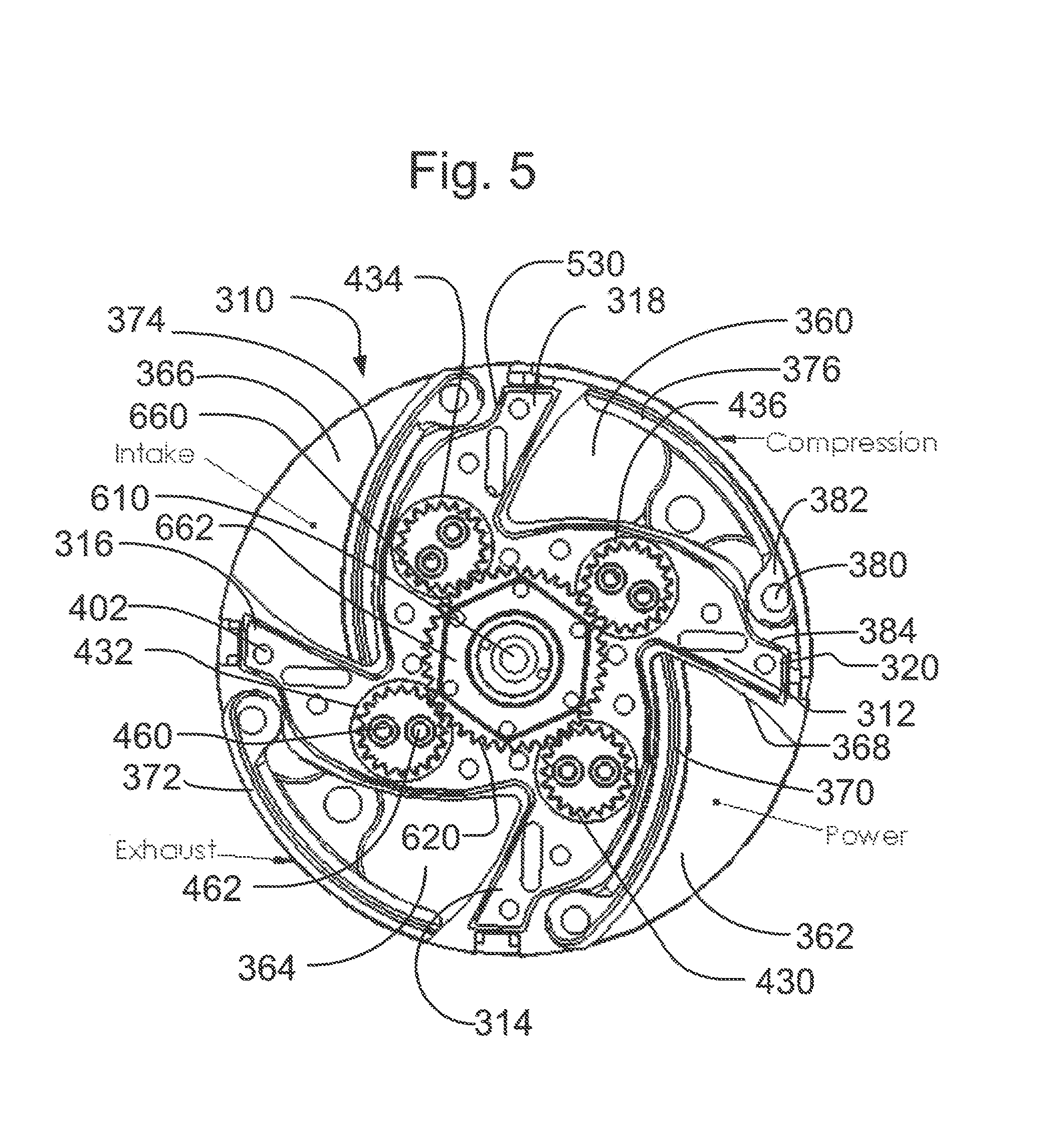
GoTek Engine Fig 5. See text for details. Click image for the largest view.
In Figure 5 the inventory of important parts are the outer circle and the innermost gear that are both non-moving parts. There is a roughly X shaped frame work, four gears at the ends of the crankshafts, four connecting rods that can barely be seen at compression and exhaust positions and four hinged flaps that make up the moving parts. That practically gives it all away.
Following the fuel and energy at the upper left into a cavity between the outer circle and the retracted flap intakes the fuel and starts the cycle. As the framework turns clockwise to the compression position at the upper right, the flap is moved out from the barely seen connecting rod that moved as the crankshaft gear pushes the connecting rod to the furthest point out. Now the fuel mix is ready for ignition.
The energy from the burning fuel’s released expanding gas pressure and heat pushes the flap back to the centerline. The energy flows through the connecting rod into the crankshaft whose gear tries to transmit it to the center stationary gear. But, the force of the energy is applied to the rotating mass of moving parts instead. When the fuel charge goes off the flap and connecting rod are moving inward turning the crankshaft journal in a half rotation pulling the framework and all the moving parts a quarter turn around. That’s the power stroke.
Momentum takes the framework another quarter turn as the crankshaft has turned another half turn and pushed the flap fully out again to complete the exhaust. Once explained it really is simple. This happens four times with each framework revolution.
What makes it confusing is the triangular shape of the combustion chamber, four crankshafts turning in a framework that also turns within a simple tube housing. Its like the expected cylinder block, crankshaft and pistons were turned inside out! That about what has happened.
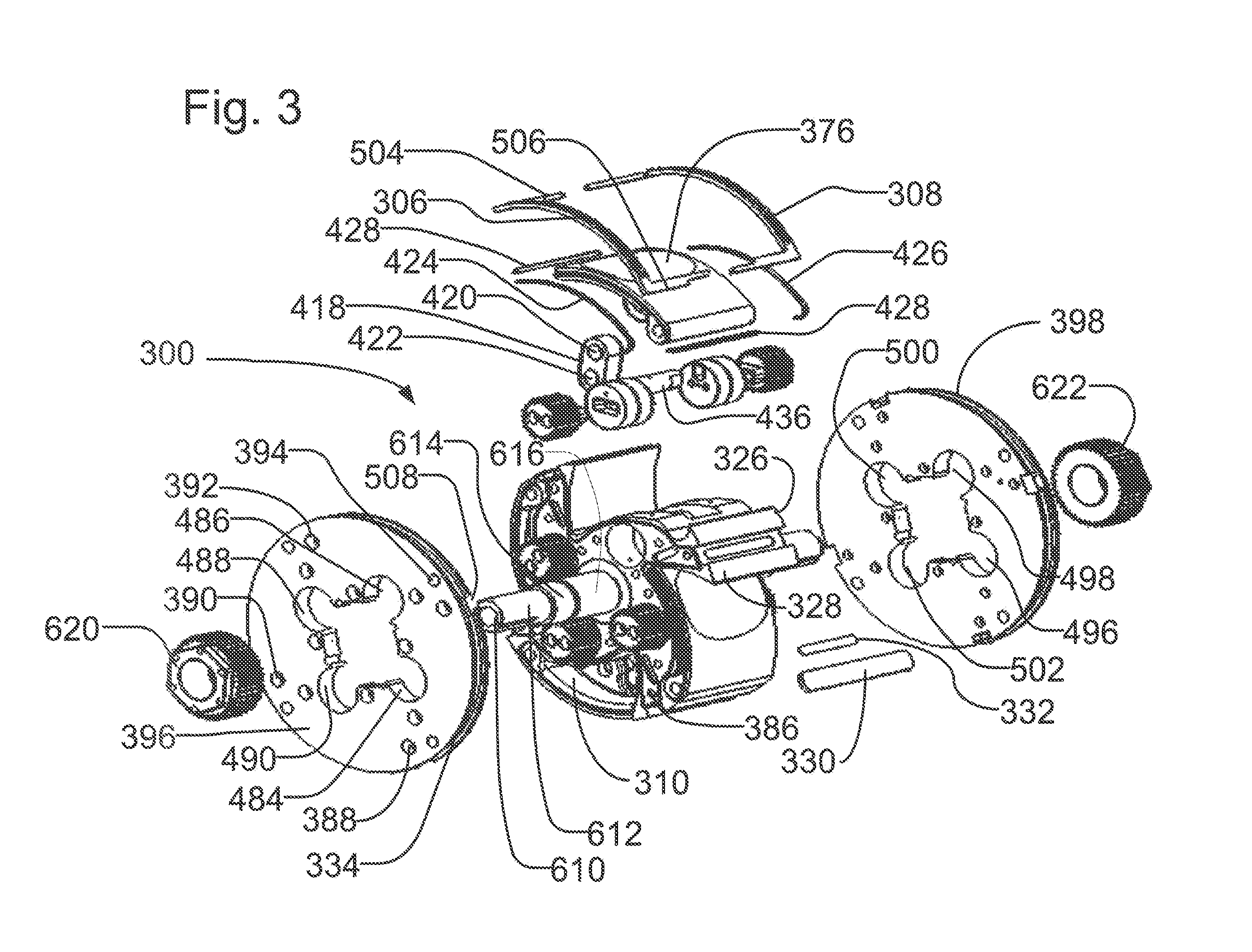
GoTek Engine Fig 3. See text for details. Click image for the largest view.
Figure 3 clarifies the connecting rod and crankshaft designs and makes the energy flow and motion more clear. The framework now looks more like a rotor and the end caps seem to be rotating parts as well as simplifying the sealing and extracting the lubricating oil.
Another point of great interest to those who have owned the famed Wankel engine is the rotating end caps greatly reduce the seal wear. A Wankel rotor side seal swept the entire sidewall but here the flap side seals need only sweep the distance of travel. That’s not much at the hinged end. Also the seal between flaps is a simple sweep in a true circle.
The GoTek looks to be naturally well balanced. The only reciprocating parts are the flaps and connecting rods that are counterbalanced opposite to each other. The engine should be very smooth indeed. With all four “strokes” completed in one revolution the smoothness will also be enhanced.
When Mazda brought the Wankel to market we were all impressed by the smoothness and the power to weight ratio. Efficiency and seal life did the engine in, but for those of us who had RX4s or Cosmos or RX7s, the memories are sweet, sweet indeed.
Some major manufacturer(s) is (are) likely to bite. Assuming the emission requirements can be handled the low production cost projections, efficiency and great size and power to weight potentials are sure to be very attractive to buyers.
Your humble writer has only one concern, that is the pumping losses on the flap side opposite of the fuel. Presumably the air will shift inside the rotor framework at a low energy cost.
Congratulations are in order for the GoTek Energy team. And a bunch of good luck too.
Comments
14 Comments so far
Feedburner
Reddit

Stumbleupon


Two concerns.
Centripetal (or old school centrifugal)force will tend to push the flaps outward, causing a loss in high rpm power; there’s a breakeven point where centripetal force will equal inward force from pressure and the strength of the connecting rod.
Cooling: There is no way to cool the inside of the flap piston other than oil splashing or high air flow.
Fewer moving parts? Only if compared to a 4-stroke engine! There’s 4 cranks, 4 conrods and pins, 4 pistons/flaps; the only things missing are the valve train parts. A two stroke or turbine has even fewer parts and can be made just as efficient and ….have there been any emissions numbers, or power numbers on the new engine?
Nest issue: same as a 2-stroke engine; the shape and placement of the ports and the timing or movement of the flaps will be critical. The flap will only be just descending as it passes the intake port and must be fully seated far enough in advance of closing the intake port to fully fill the combustion area. Same in reverse for exhaust. But, this means that for every revolution of the whole engine, the piston flaps must move in and out 4 times. This means a vibration rate equal to that of a valve on a diesel 2-stroke. The length of movement will be a compromise between power and torque.
I agree with the crankcase air movement issue, as well as centrifugal oiling issues.
Engines are complicated, and it never hurts to take a stab at improving what we have. But the proof will be in the performance, put one in a race car.
Second to last thing; this article was written like the rotary engine is dead, which is hardly the case. The latest generation of rotary engines is quite powerful and the seal issues have been mitigated. The problem is, if you take a look at the RX-8, efficiency is just not there. Power equals fuel burned, add to that the emissions requirement from the EPA (at least for gasoline)and you have an almost mandated maximum efficiency.
The trick has always been to make the most Useful energy for the fuel burned. The old hit n miss engines were slow and not super powerful, but they could make low RPM monster torque all day (with lots of bad emissions). Modern 4-strokes and diesels also make useful power. The only way a turbine makes useful power is through a massive gear reduction and ensuing power losses or mechanical failures (think indy car from the 60’s). If this engine is to make useful power, it’s output should fall within the 0-5000 RPM range. Because the flaps are vibrating 4 times the rate of the output, max RPM might be too low. Simple calculation: say the engine is spinning at 2000 RPM, flaps vibe at 8000 times per minute, which is 133 times per second. Throw in the g-forces and assume length of travel on the far end of the flap, and the ensuing torque from the rapid pivoting, and the forces will add up fast.
Lastly, editing and proofing is a must. “that is the pimping losses on the…” Pimping???
Thanks! The pimp now pumps. Your thoughts and critiques are quite welcome, any more?
Not too worried about pumping loss on the crank case side, as the internal volume should remain the same. With two flaps compressing and two flaps retracting. More importantly is the use of frition reducers and scavenging, oil recovery from the crankcase posses a unique challenge.
GoTek Energy, Inc. appreciates the enthusiasm as well as the critiques our DynaKinetic rotary engine design has generated in your article. Taking into consideration feedback from technical sources is something we always feel is important.
We want to say that “New Energy and Fuel” did a very nice job of analyzing our initial base architecture patent to clarify our engine’s operation. It inspired some great thinking and comments as well from your readers.
We felt it was important to take some time to respond to Jon’s detailed comments about our engine.
On the issue of centripetal effects versus RPM, from a power standpoint the force acts to aid on compression and exhaust cycles (BDC-to-TDC movements). In contrast and as noted, it acts to hinder on intake and power cycles (TDC-to-BDC movements). From an energy standpoint, there is balance. From a force and stress standpoint, intake and power cycles do need to consider the increased tension forces created on the rod and our points of rotation. Key points to note are that our rods are 1 piece with no bolted end caps and advancements in the rotation point robustness have occurred. Although our engine has centripetal influences which many other engines do not, it should be noted that our reciprocating mass is significantly less (over 70% less than a piston engine) which yields major gains as RPM increases!
On the issue of pivot piston (flap) cooling, our pivot piston’s underside oil cooling is no different than a piston engine other than slinging it to the underside is easier.
On fewer moving parts, we have a significant reduction compared to a piston engine. The number of moving parts in a valvetrain is significant. We have none of that. Granted we have more than a Wankel but compromises on torque and efficiency were made to achieve the Wankel’s 1 moving part. Likewise, the turbine has an open combustion chamber and needs very high RPM to achieve the best efficiency of any engine but at high cost and without motor vehicle applicability.
On efficiency of other engines, the turbine is great at high RPM and altitude but not for ground based vehicles. The 2-stroke has emissions issues and that’s exactly why we do not see it in mass use today and in most cases it is being replaced with 4 cycle engines where it does exist.
On ports, the relative placement of intake and exhaust ports do control overlap. The circumferential length determines duration. The shape determines lift. These are important tuning factors but they are no more critical than the tuning of a piston engine’s cam. We can do it with a sleeve. Additionally, the cam’s mechanical timing relation to the crank is no different than our rotor/piston’s mechanical timing relation to the ports.
On vibration and pivot piston movement per main crank rev, our mini-cranks move at twice and not four times the speed of the main crank. A piston engine has 2 of its 4 cycles executed per main crank rev. The DynaKinetic engine has 4 of its 4 cycles executed per main crank rev. It should also be noted that 180 degree opposing pivot pistons are always perfectly balanced no matter where in operation they are at.
On crankcase pressure, there is balance with high flow passages between chambers below the pivot pistons so there is no issue.
On oiling evacuation, there were challenges to consider and we have addressed those with the right design features, leak path controls, flows, and dry sump oiling system.
We agree that testing in application is the proof and we continue to progress to achieve those goals. Completion simply takes time and money.
In summary, we agree the rotary engine is not dead and there are many great things happening on the internal combustion engine front. Stayed tuned as we make a difference with DynaKinetic power!
Thanks Scott. BW
Technology Submission -State of the Art – Novel InFlow Tech – Featured Project Development; 1-Gearturbine, 2-Imploturbocompressor
1-GEARTURBINE PROJECT
Rotary-Turbo-InFlow Tech
Atypical InFlow Thermodynamic Technology Proposal Submission Novel Fueled Motor Engine Type
*State of the art Innovative concept Top system Higher efficient percent.*Power by bar, for Air-Planes, Sea-Boats, Land-Transport & Dynamic Power-Plant Generation. -Have similar system of the Aeolipile Heron Steam device from Alexandria 10-70 AD. -New Form-Function Motor-Engine Device. Next Step, Epic Design Change, Broken-Seal Revelation. -Desirable Power-Plant Innovation.
YouTube; * Atypical New • GEARTURBINE / Retrodynamic = DextroRPM VS LevoInFlow + Ying Yang Thrust Way Type – Non Waste Looses
-This innovative concept consists of hull and core where are held all 8 Steps of the work-flow which make the concept functional. The core has several gears and turbines which are responsible for these 8 steps (5 of them are dedicated to the turbo stages). The first step is fuel compression, followed by 2 cold turbo levels. The fourth step is where the fuel starts burning – combustion stage, which creates thrust for the next, 5th step – thrust step, which provides power to the planetary gears and turbines and moves the system. This step is followed by two hot turbo steps and the circle is enclosed by the final 8th step – bigger turbine. All this motion in a retrodynamic circumstance effect, wich is plus higher RPM speed by self motion. The Reaction at front of the action.
*8-X/Y Thermodynamic CYCLE – Way Steps: 1)1-Compression / bigger 2)2-Turbo 1 cold 3)2-Turbo 2 cold 4)2-Combustion – circular motion flames / opposites 5)2-Thrust – single turbo & planetary gears / ying yang 6)2-Turbo 2 hot 7)2-Turbo 1 hot 8)1-Turbine / bigger
-With Retrodynamic Dextrogiro vs Levogiro Phenomenon Effect. / Rotor-RPM VS InFlow / front to front; “Collision-Interaction Type” – inflow vs blades-gear-move. Technical unique dynamic innovative motion mode. [Retrodynamic Reaction = When the inflow have more velocity the rotor have more RPM Acceleration, with high (XY Position) Momentum] Which the internal flow (and rotor) duplicate its speed, when activated being in a rotor (and inflow) with [inverse] opposite Turns. The Reaction at front of the action. A very strong Novel torque power concept.
-Non waste parasitic looses for; friction, cooling, lubrication & combustion.
-Shape-Mass + Rotary-Motion = Inertia-Dynamic / Form-Function Wide [Flat] Cylindrical shape + positive dynamic rotary mass = continue Inertia positive tendency motion. Kinetic Rotating Mass.
-Combustion 2Two continue circular [Rockets] flames. [ying yang] opposite one to the other. – With 2TWO very long distance INFLOW [inside propulsion] CONDUITS. -4 TURBOS Rotary Total Thrust-Power Regeneration Power System. -Mechanical direct 2two [Small] Planetary Gears at polar position. -Like the Ying Yang Symbol/Concept.
-The Mechanical Gear Power Thrust Point Wide out the Rotor circumference were have much more lever [HIGH Torque] POWER THRUST. -No blade erosion by sand & very low heat target signature profile. -3 points of power thrust; 1-flow way, 2-gear, 3-turbine. *Patent; Dic. 1991 IMPI Mexico #197187 All Rights Reserved. Carlos Barrera.
—————————————
·2-Imploturbocompressor; One Moving Part System Excellence Design – The InFlow Interaction comes from Macro-Flow and goes to Micro-Flow by Implossion – Only One Compression Step; Inflow, Compression and outflow at one simple circular dynamic motion Concept.
*·“Excellence in Design” because is only one moving part. Only one unique compression step. Inflow and out flow at the same one system, This invention by its nature a logic and simple conception in the dynamics flow mechanics area. The invention is a wing made of one piece in a rotating motion, contained in a pair cavity system connected by implocavity, and interacting dynamically with a flow, that passes internally “Imploded” through its simple mechanism. This flow can be gas (air) or liquid (water). And have two different applications, in two different form-function; this one can be received (using the dynamic flow passage, as a receiver). Or it can be generated (with a power plant, generating a propulsion).
An example cut be, as a Bike needs a chain to work from motor to wheel. And for the Imploturbocompressor application, cut be as; in a circumstance at the engine, as an A-activate flow, and with a a tube flow conduit going to the wheel as a B-receiving-flow the work use.
To see a Imploturbocompressor animation, is posible on a simple way, just to check the Hurricane Satellite view, and is the same implo inflow way nature.
And when the flow that is received and that is intended to be used at best, must no necessarily by a exhausting or rejection gas, but must be a dynamic passing gas or liquid flow with the only intention to count it or to measure it. This could be possible at the passing and interacting period when it passes inside its simple mechanism. This can be in any point of the work flow trajectory.
In case the flow that is received is a water falling by gravity, and a dynamo is placed on the rotary bar, the Imploturbocompressor can profit an be obtained by generating? electricity such as obtained by the pelton well, like I say before. The “Imploturbocompressor”, is a good option to pump water, or a gas flow, and all kinds of pipes lines dynamic moves.
Or only receive the air-liquid flow, in order to measure its passage with a counter placed on the bar, because when this flow passes through the simple mechanism of a rotating wing made of only one piece it interacts within the implocavities system. And this flow can be air wind, with the difference of can have an horizontal work position, and that particle technical circumstances make an easy way for urban building work new use application, and have wind flow from all the sides 180 grades view. The aforementioned information about this invention refers to technical applications, such as a dynamic flow receiver. (whether being gas or liquid).
With the appropriate power plant and the appropriate dimensioning and number of RPM this invention is also feasible to generate an atmospheric air propulsion and the auto-propulsion of an aircraft. Being an effective and very simple system that implodes and compresses the atmospheric air permits the creation of a new concept of propulsion for aircrafts, due to its simple mechanism and innovative nature. At the place of the aircraft were the system appears and the manner how the propulsion direction can be oriented with a vectorial flow (no lobster tail) with I call “yo-yo system” (middle cut (at the shell) to move, one side loose), guided and balanced is feasible to create a new concept of TOVL-vertical take-off landing, I wish good for a wild conditions. Because the exhaust propulsion can going out radial in all the 360 vectorial positions, going out direct all the time in all the vectors direction. With his rotor cover for an better furtive fly, like going down of a bridge for example.
Likewise, with the due form and dimensioning, and considering the liquid density and the due revolutions for this element there could be generated a propulsion (water) in order to move an aquatic ship, whether on surface or under water. Also can be a good option to pump liquid combustion for a rocket propulsion.
Making a metaphoric comparison with the intention to expose it more clearly for a better comprehension of this innovative technical detail, it would be similar to the trajectory and motion of a dynamic flow compared with a rope (extended) that passes through the system would have now a knot (without obstructing the flow), so the complete way of the flow at the imploturbocompresor system have three direct ways and between make two different turns; direct way (entrance) – turn – direct way (implocavity) – turn – direct way (exit), all this in a 1 simple circular move system concept.
Its prudent to mention that the curves and the inclinations of the blades of a rotating wing made of this invention, is conferred by its shape and function a structural rigidity allowing it to conduct and alter appropriately the dynamic flow passing through its system.
any consideration being made for ceramic composite parts having superior wear and mechanical properties?
the website should support/explain the above.
Dear Sir,
If you send an e-mail me, I will send you information about my work on the Wankel rotary engine.
I am an inventor and I have no particular material, look for a research center to put into practice my work in a newly developed rotary engine with the ideas of my project BRUNTOR. My job, I’ve put into practice in a rotary engine that got SACHS with outstanding results that will send you.
After verifying the outstanding results achieved with my work, develop a new rotary engine may be the best internal combustion engine invented by man and also a motor “green.”
The most important idea of my project – called NEW DESIGN – ensures permanent seal between the chambers of the motor, this idea is patented.
With the idea – NEW DESIGN – The rotary engine is best suited to consume hydrogen.
Greetings: eliasbruno23@yahoo.es
BRUNTOR. BRUNO – ROTOR. Elias BRUNO Ribeiro.
========= =============== ================
The IMAGINATION can build the knowledge,
the knowledge can LIMIT the IMAGINATION.
====================================
The report “A Review of Heavy-Fueled Rotary Engine Combustion Technologies” from the Army Research Laboratory (ARL) identifies the cause of poor emissions and economy in Wankel rotaries.
Many of the design issues identified in the ARL report are present in the GoTek design:
o Large combustion chamber surface area
o Quenching due to combustion chamber shape
o Recessed spark plug
o Poor flame propagation
o Large seal area
The GoTek website dedicates a lot of space to discussion of the improved lever arm yielding increased torque. It’s of some concern that the inventor appears to think work is created by the lever. It’s not. Work in an internal combustion engine is produced by the Pressure, Volume, and Temperature (PVT) less losses to combustion chamber surfaces, gas pumping, and friction. These factors are rolled up into Brake Mean Effective Pressure (BMEP) and Brake Specific Fuel Consumption (BFSC) which describe everything about a motor’s performance without ever discussing levers.
Torque is simply the product of force and lever length. For a given force, a longer lever produces more torque, but the lever has to move further which means the pistons have to move faster for a given RPM. Those same elevated piston speeds could be used to create greater RPM, but they are employed to produce torque rather than RPM. Thus, the longer lever is simply a transmission. It doesn’t increase work performed by the engine.
The GoTek rotary is mechanically clever and seductive. I humbly predict, however, that it will yield performance, efficiency, and emissions similar to the Wankel, but with a greater complexity. If there is improvement, it will be minor and incremental.
Right, Rod. Thanks for the contribution.
Hi Rod, I’m not sure I understand the significance of your comment on torque. When I consider the common Otto engine, lets say a max pressure of 700 psi and a crank angle of 10 degrees ATDC, the energy converted to work (pressure on piston) suffers because of poor lever arm size (most of the energy is directed to crankcase and not rotational energy). If, lets say, 10% of the available pressure is used for rotational energy, the other 90% is wasted at that moment.
Lets say we jump ahead a few milliseconds and the crank is now at 65 degrees ATDC, the lever arm is larger now, however, pressure is further reduced in the cylinder so that the actual pressure energy converted to rotational energy suffers from lower cylinder pressures.
I am not sure this has anything to do with speed versus torque tradeoffs when it comes to efficiency. efficiency is the result of a million snapshot moments of energy available (pressure) and torque angle available (lever arm size for Otto). What do you think?
Sorry Rod,
“I am not sure this has anything to do with speed versus torque tradeoffs when it comes to efficiency. efficiency is the result of a million snapshot moments of energy available (pressure) and torque angle available (lever arm size for Otto). What do you think?”
I should have said,
I am not sure this has anything to do with speed versus torque tradeoffs when it comes to efficiency. efficiency, (among other things), is the result of a million snapshot moments of energy available (pressure) and torque angle available (lever arm size for Otto). What do you think?
When Mazda brought the Wankel to market we were all impressed by the smoothness and the power to weight ratio. Efficiency and seal life did the engine in, but for those of us who had RX4s or Cosmos or RX7s, the memories are sweet, sweet indeed.
This is an engineering team to take note of, this concept may well be in your car of the future.